| T O P I C R E V I E W |
| EDZIP | Helping a buddy with a 1999 Prowler fuel gauge initially goes up the down as car is started. The fuel gauge has "4" pins on the back. With key on one has 12v, one showed 330 ohms which corresponds with a 1/3 full fuel tank. (He installed a new sending unit). He sent the instrument cluster out for rebuild, I have doubt about the printed circuit boards being bad because the gauge is getting both power and the ohm output. "Anyone have a schematic of the fuel gauge so I can understand how the BCM ties into the gauge." Thanks |
| padroo | This is out of my 1999 manual.
Let us know how it turns out.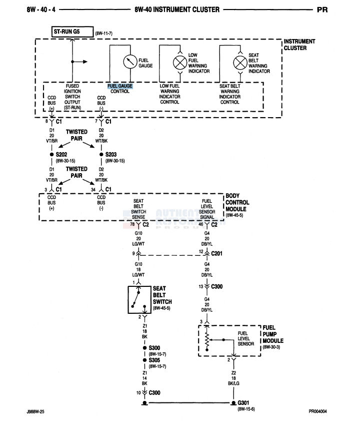
Ground G301 is located on the right side of the transaxle. Black/ Lt. Green wire. This message has been edited by padroo on 06-13-2018 at 10:13 AM |
| robin | http://www.prowleronline.com/ubb/Forum1/HTML/006190.html History of 99s having gas gauge issues. |
| Tomcal |
A couple of things.Did you do and instrument self-diagnostic test? To do this, depress odometer trip reset button while turning key to on/run. It will sequence through all gauges. When sequence gets to fuel gauge it should read 3/4. Connection between BCD and instrument cluster is a serial data stream (Twisted Pair). Very difficult to diagnose without a serial data analyzer. When you say fuel gauge has 4 pins. Are you referring to connector at fuel pump module? If so, you should be reading a voltage with key on at pin 3, not ohms. Since gauge is moving it most likely is not the gauge itself but electronics driving gauge. Fuel sending unit is very fragile and could have been damaged on installation. It comes down to three things; Fuel sending unit
BCD
Instrument cluster electronics.
|
| EDZIP | Thanks to all for your contribution Tomcal The fuel gauge has (4) pins on the back, the schematic by "padroo" doesn't show the pin out for the gauge. Wish that I took a picture of the four terminals on the gauge itself or even noted the printed digits from each pin. There was 2 with a + symbol and 2 with a - symbol. Wasn't aware of the self test procedure.. What we did was put jumper wires on one + and one - terminal and put the cluster back in. With the key on the + terminal read 12v, the - terminal read about 330 ohms which would be approx 1/3 tank since the sending unit max's out at 1000 ohm full. (tank is about 1/3 full) We assume that with the OHM reading of 330 the sending unit is sending the resistance reading to the gauge via the sending unit and cluster. Not knowing which set of terminals actually control the fuel gauge reading , we assume that one set of (+/-) terminals control the fuel level display and the other set of (+/-) control the low fuel level warning light. So if I had the actual fuel gauge "pin out" it would help with diagnostics. As you know the fuel gauge light is displayed via the fiber optical transfer from a light bulb on the circuit board. |
| NiteProwl64 | Hope this helps... 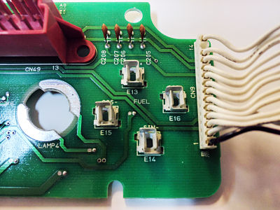
|
| NiteProwl64 | And this... 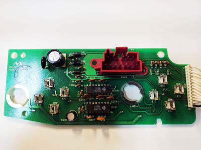
|
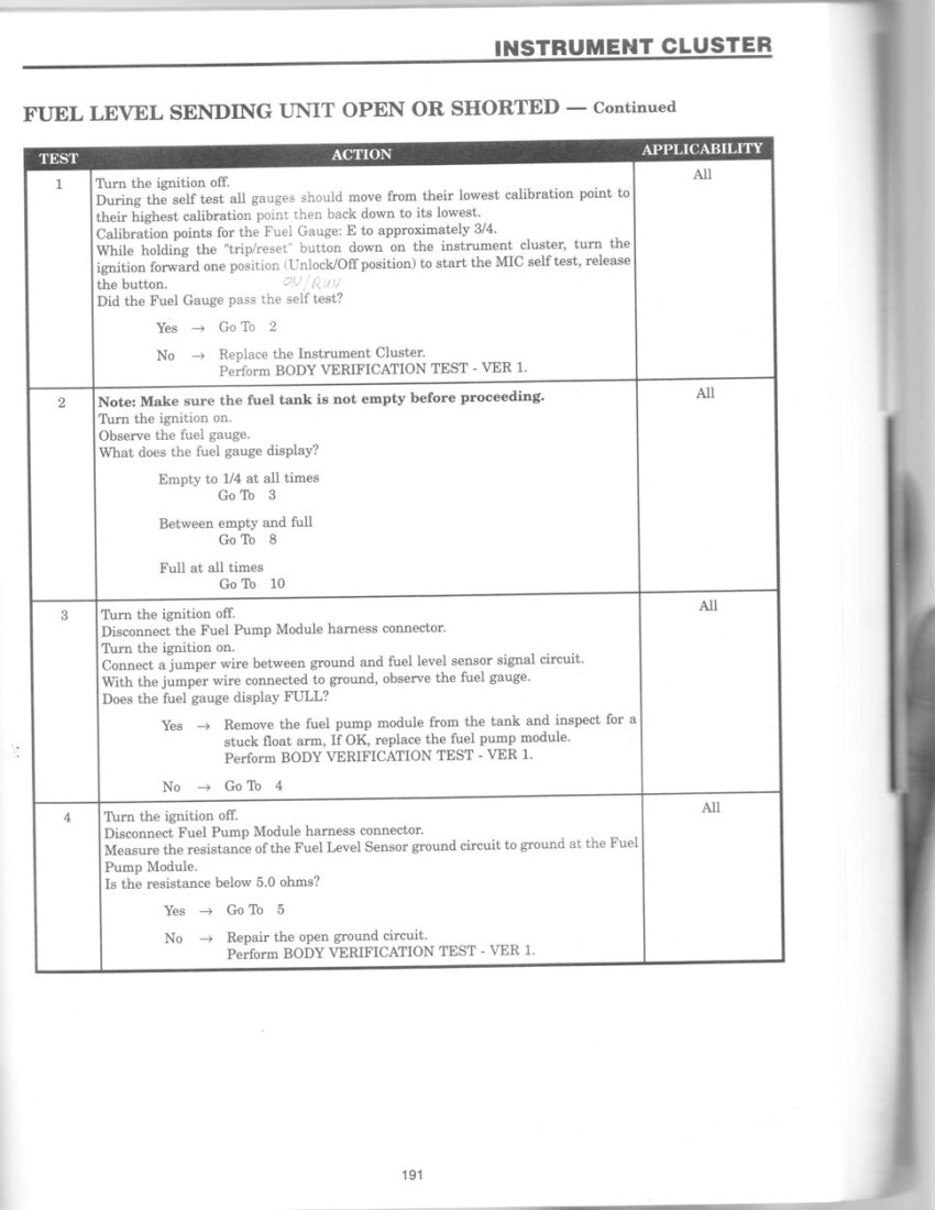
| Tomcal | OK, but you should still be reading Volts not Ohms. Fuel gauge is analog, driven by volts. I would try checking voltage at fuel pump, fuel level sensor. You can also check resistance (ohms) of sensor as shown in procedure below. This would eliminate it being the fuel level sensor. Below is the full diagnostic procedure from a year 2000 diagnostic manual; ...Note there are some minor errors in manual that will not effect diagnostic...
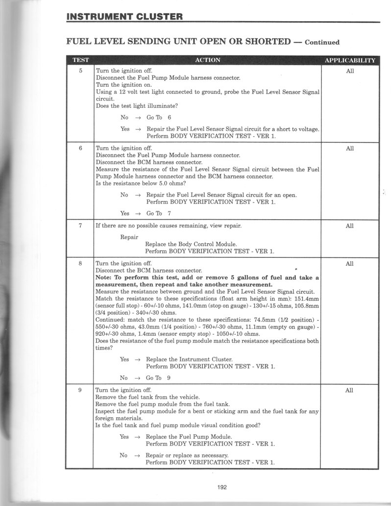
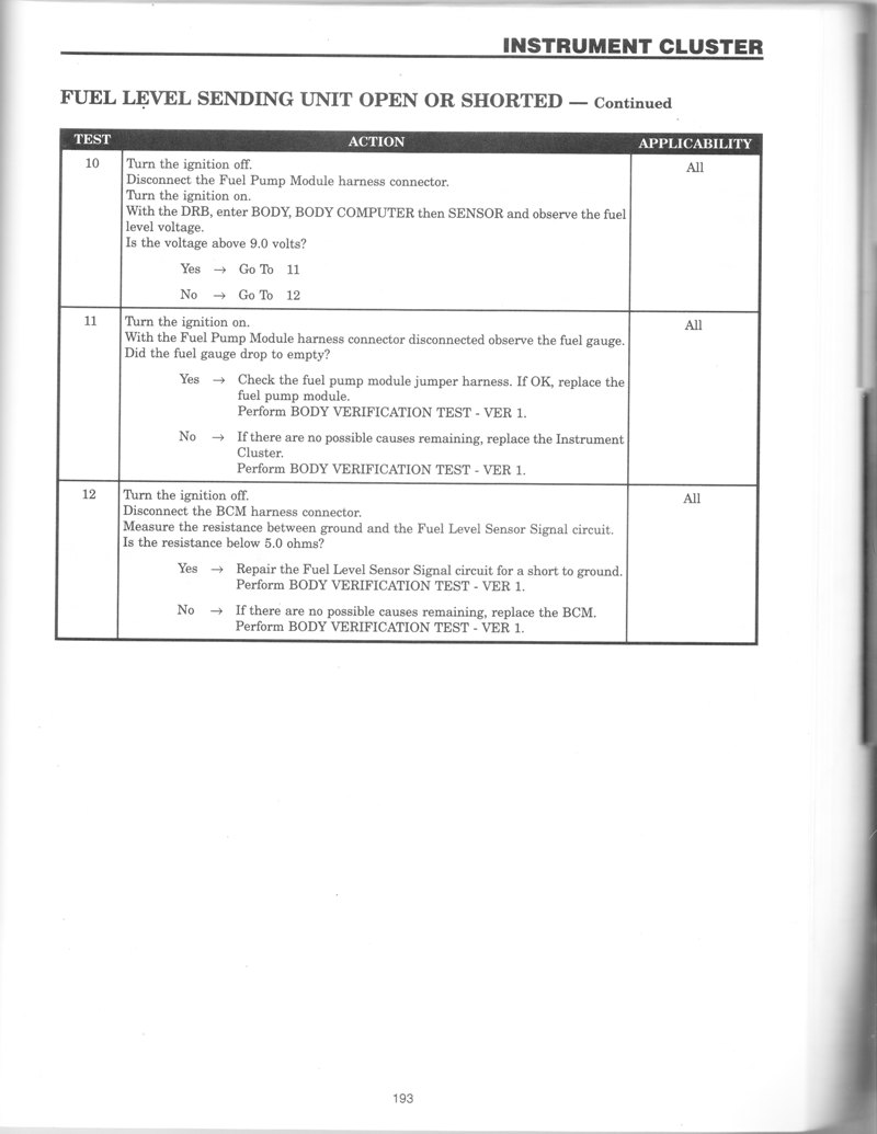
This message has been edited by Tomcal on 06-14-2018 at 02:11 PM |
| EDZIP | quote:
Originally posted by Tomcal:
OK, but you should still be reading Volts not Ohms.Fuel gauge is analog, driven by volts. I would try checking voltage at fuel pump, fuel level sensor. You can also check resistance (ohms) of sensor as shown in procedure below. This would eliminate it being the fuel level sensor. Below is the full diagnostic procedure from a year 2000 diagnostic manual; ...Note there are some minor errors in manual that will not effect diagnostic...
Thanks...my experience is working with GM 0-90 ohm sending units. I supply 12v to the gauge and the sending unit controls the variable ground to the gauge which in turnm moves the gauge up/down. Isn't that the same principal with the Prowler?
|
| EDZIP | quote:
Originally posted by NiteProwl64:
Hope this helps...
Thanks that's the pic I should have taken. With key on E13 has 12v and E14 has approx 330 OHM (1/3 tank value).
Would like to know how E15 and E16 work in this equation.
|
| Tomcal |
Regarding E15 and E16. Need to see picture of back side of circuit board to follow traces. |
| Tomcal |
EDZIP...Regarding comparison to GM, yes you measure Ohms or Volts per manufactures instructions. However, it depends on the location your probing. On a Prowler, signal from fuel level sensor, a varying resistance (Ohms) to ground, is sent to BCD. BCD converts varying Ohms to an analog voltage and then encodes that to a serial digital data stream. Once it's a serial data stream, there is no Ohms or Volts you can measure with a Multi-Meter. BCD sends digital data stream to instrument cluster which decodes signal back to analog volts, which then drives gauge. Bottom line is you can measure Ohms at fuel level sensor once you disconnect it from BCD. But, at gauge in cluster you must measure volts. It's not a simple straight wire from level sensor to gauge on a Prowler or other Chrysler products. Follow step 8 in diagnostic procedure and read ohms of sensor to see if sensor is bad. It's probable easier to disconnect connector at fuel pump module to take reading. BCD is difficult to reach. You can also remove fuel pump module (access in trunk) and manually move sensor lever arm and see how gauge reacts.(not that hard to remove) Let me know if I can help further.
... |
| EDZIP | Thanks Tomcal He installed a new sending unit and it displays the proper ohm range manually (unplugged). Don't remember the exact float ohm range but it was in the 50 empty to 1000 full range. So the problem is from the BCM forward, he did send the cluster out to a Prowler repair shop and they were upfront that they doubted the gauge itself was bad. The only positive will be that the printed circuit boards will be checked. One option in the back of my head is possibly installing an aftermarket fuel gauge and simply bypass the BCM....but without a detailed schematic (which might be over my head anyway) I can't determine if that would affect bcm functions. (ie low fuel indicator) Locating a 50-1000 ohm fuel gauge is probably impossible...so the tank sending unit would need to be matched up with the gauge ohm range. Converting to a generic (old school) 0-90 ohm tank sender controlling a 0-90 ohm 2 wire gauge (maybe even digital display) would be surely be less complicated and reliable. I use them on my street rods. Kinda hoping they identify a problem with the cluster |
| EDZIP | As an update only...the Prowler cluster repair shop said the fuel gauge was faulty...waiting for the repaired unit to be returned. |
| Tomcal |
Thanks for keeping us updated.Let us know results when repaired cluster is re-installed. |
| padroo | Here is the instrument cluster PIN OUT. There is no wiring diagram of the internal workings of the instrument cluster. 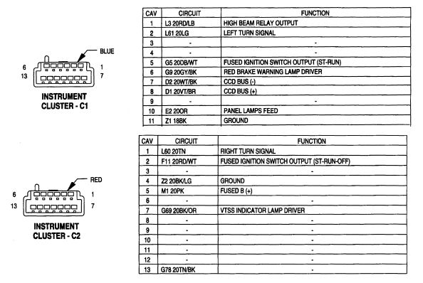
This message has been edited by padroo on 06-17-2018 at 05:20 PM |

